In the 5th module, Smart Technology, we as students were taught how to measure different quantities using sensors, design systems with a certain goal in mind and the basics of Control systems. Listed on this page are some of the systems that I designed in collaboration with various students. We were made very familiar with the workings of an op-amp and used amplification in our feedback systems as well as in our filters.
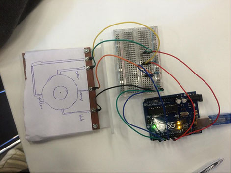
A capacitive touch-wheel was interfaced using an Arduino as a micro-controller where the values of the capacitance were collected and the region of the touch wheel where contact was made was determined.
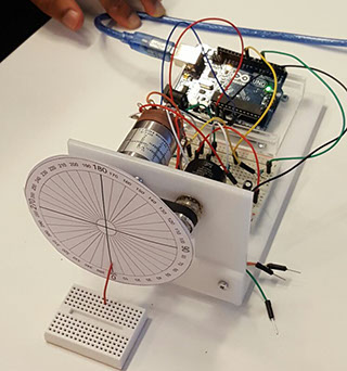
The angle of wheel was controlled using PID control. The motor was given an angle or set-point in a program and the system turned the wheel to the set-point. We tuned the system so that the response was fast with a minimal offset. This was a particularly fun exercise as we tried to get the wheel to the set-point as fast as possible with barely any overshoot.
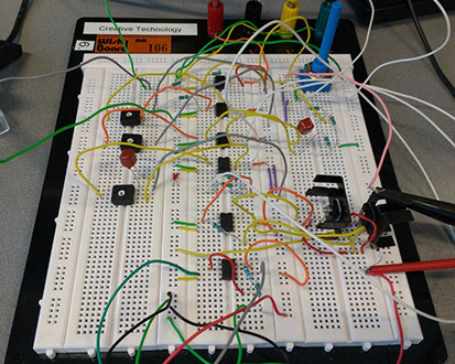
In our Circuits and Electronics course, we designed a filter system using op-amps that separated a fetus' heart rate signal from a signal coming from an ECG attached to the abdomen of a mother. The system took the mixed signal of the fetus' and mother's heart rate on one channel, and the signal of just the mother's heart rate on another channel and filtered out the mother's heart rate leaving only the fetus' heart rate to be heard on the audio output.
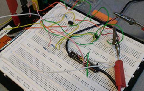
In the Control Systems course, we were tasked with creating a PID control for the temperature of a power resistor. We built a system using 6 op-amps of which there were inverting amplifiers and summing amplifiers in order to implement PID control. The practical was a resounding success as we had a constant error between the desired value of the temperature and the actual value of the temperature of less than 1 degree Celsius.