For the big group project of this course, I joined team 2 with some people I met during the session in week 2. Our group had a nice diverse mix of studies (ID,I-tech, EE, Psychology) which was very fun to work with. The first assignment was pitching two domains we could envision making more tinker-friendly. During our brainstorming session many ideas floated around (C&C machines, making robots from kitchen utensils) but apart from the two we chose we didn’t write them down so sadly I cannot give a longer list. The two ideas presented were a click-bot-derived easy robot building kit and a modular wearable prototyping kit. We chose to continue with the second idea because it seemed the most “new” and it got the most positive feedback during our pitch.
First Concepts
With our domain selected, we began developing some mock-ups and sketches. The goal with our kit would be to give people a low-risk way to investigate how wearable technology works and alleviate some of the black-box effect where people have no idea what goes on inside their devices. Wearables are especially suited for this because they are some of the most difficult devices we own to take apart. A screwdriver can get you quite some ways into most laptops but wearables are a lot more involved and pose significant risks to the device.
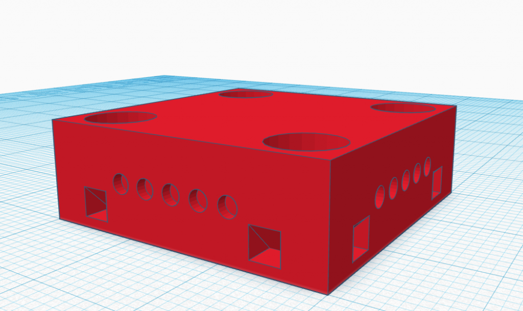
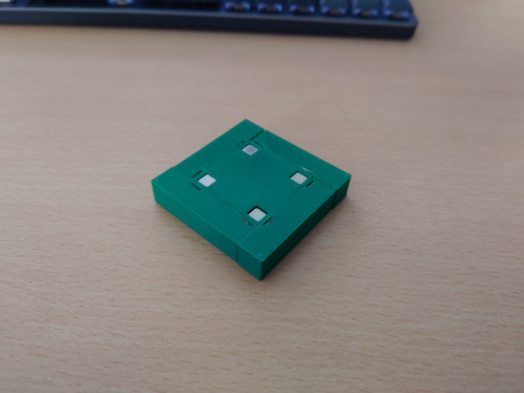
In spirit of this year’s theme we started looking into magnetic modules which would snap onto a central unit. We made some 3D mock-ups of this in tinkercad and printed them to see what it could look like and if we liked it. The first version used two little teeth to guide a module into place but this didn’t work great with the magnet solution and could still be inserted upside down. The proportions of the magnet holes also weren’t correct in this version which is why they are missing from the printed parts.
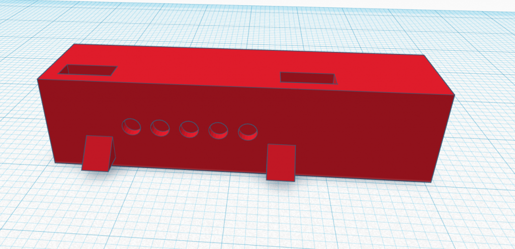
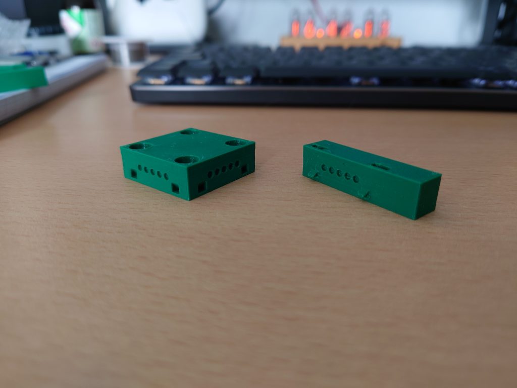
This design was improved in the second version which used a different connector to connect the centre piece and the modules. The connector was keyed to only go in one way to aid affordance and the magnets in the hub pieces were changed to pieces of scrap metal since the magnets in the corners of the centre piece can’t hold two magnets at a corner like in this mock-up.
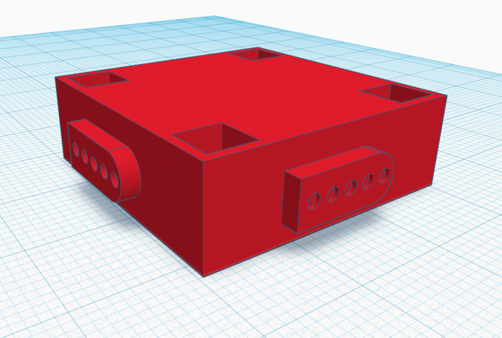
The big goal with these first mock-ups was to look at ways where the modules could be connected to the main piece through the same universal connector. One of the properties of a successful tinkering material is the amount of ways its building blocks can be connected together. This is difficult to realize in a material which has a set number of connection points (in the mock-up above there’s four connection points) since it can’t be extended indefinitely like a toy building block. Still, we tried to get as close as we could which is why we modelled a universal connector like the pictures above show. We also envisioned some modules which could accept their own customisation, i.e. the user could attach more to the module or use it to develop something else. Examples are a servo-module, a module which could easily accept cardboard mock-ups or a small game controller module which could be used to develop games. We also tried to come up with as many module types as possible to make the system as customisable as possible. The document containing these ideas sadly seems to have disappeared from our collective drive (a modified version is included in the zip-file) but it included standard smartwatch components like screen (round, square or other formfactors), heartrate sensor, blood-oxygen sensor, GPS, haptic motor, speaker, microphone, step-couter and some others. It also contained a list of more niche components which could be fun to play/imagine with like button-pad inputs, CO2 meters, compasses, an input crank (like the playdate), LED-matrix and more which I can again sadly not find on the drive.
Refinement
Refining this concept started with formulating a clear goal and target user base. We came up with two distinct directions and user groups to pivot towards. One was squarely educational, aiming to teach kids in a fun session how wearable technology works and what they could do with it. The other direction would be a more advanced kit aimed at professionals of fields outside technology who want to work with wearable technology to see whether it fits their workflow.
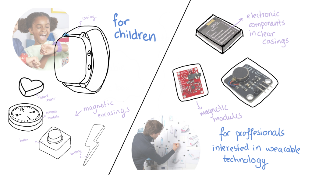
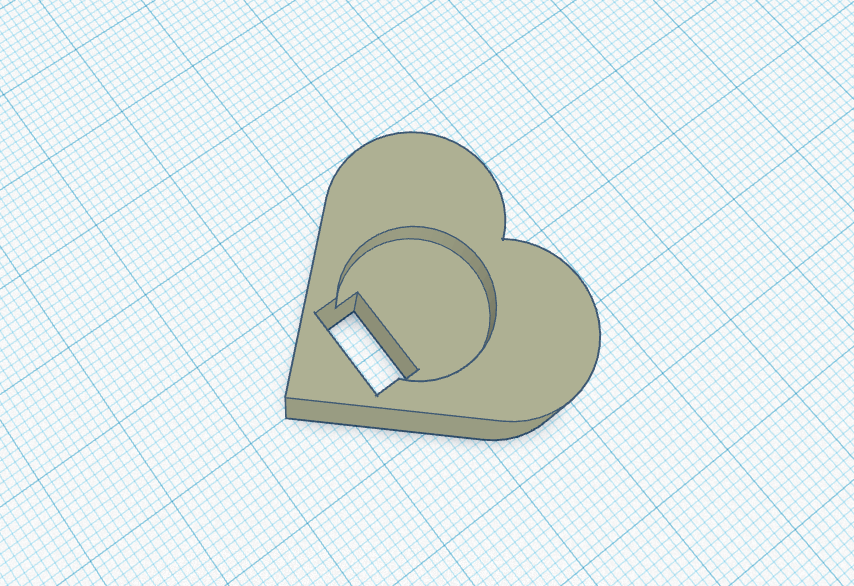
We chose the first idea, since it was closest to the original goal of giving people more insight into the inner workings of their wearable tech and we could better envision a fun tinkering session in this setting. The modules would each get a casing to signal their use-case (heart around the heartrate sensor) for easy identification and playing.
When designing the session, we quickly decided we wanted to incorporate decomposition as a scaffolding tool. It’s perfectly suited for our goal of education and would be a perfect first step when working with our envisioned toolkit. However, we weren’t sure whether this would be enough scaffolding to get people comfortable with the toolkit so we chose to incorporate a second scaffolding exercise. The design of the tinkering session is elaborated upon in great detail in the handed in zip-file but in short would look like this:
- Groups of 4-5 children get one of the toolkit wearables to play with and disassemble where they would be tasked with matching each component they take off to a specific function. The display would give cues like “Heartrate Sensor Disconnected!” when the heartrate sensor was pulled off.
- Once the components have been identified, groups would be tasked with creating a wearable that does one specific function. Here, the idea is that the group gets a bag of modules and they select the one which satisfies the requirement. The components they need to add should not have come with the kit in step one, so they see any module can be connected.
- After step 2, the groups would be given an open-ended design challenge to really begin tinkering with the wearable kit. At this point they have seen what the possibilities are and by giving challenges which can be done in many ways we hope to stimulate creativity and get groups to experiment with what they can add to the kit.
For step 2 and 3, we created some cards which would give the design challenged needed in these steps. Below are a few examples:
Example card for step 2
Example card for step 3
In comparison to some examples given during the course, this may seem like a lot of scaffolding exercises. We chose to do this because people aren’t used to taking apart their smart devices and it could be intimidating to just give them a device and tell them to rip it apart. We want to avoid handholding but do feel people need to be guided through beginning to work with something like this. The risk faced with this is that people won’t want to actually put their own creativity into this if they’re just shown what to do. They might try just to do things “right” instead of being okay with making mistakes or fall into boredom because there’s no challenge. We’ve not been able to test this but for now we feel our scaffolding is at a nice balancing point where each step gets users more comfortable with the material but also introduces new ways to use the material to keep them engaged and “in the flow”.
Prototype
When work began on the prototype, it became clear quite quickly building this actual kit wasn’t feasible. Developing a universal connector like we envisioned takes a lot of work, especially since all the modules would have to be able to communicate over it and the central unit would need to know what each component is. This essentially means giving each module its own processing capabilities to advertise what it is and convert whatever input or output it receives to what its components can use. Thus, we chose not to focus on this for the prototype but rather develop a low-fi prototype which had some disconnectable modules and a small display to give a feel of what it could look like.
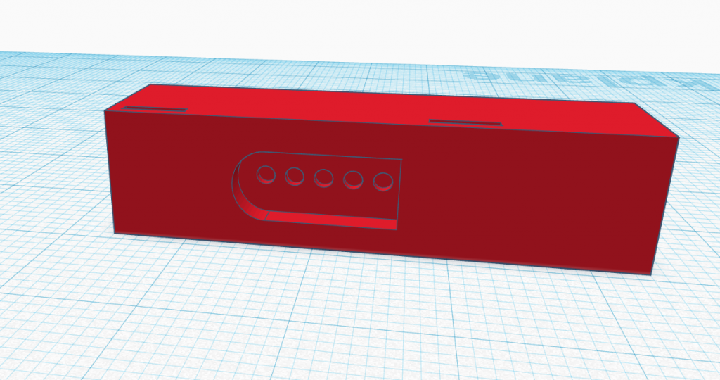
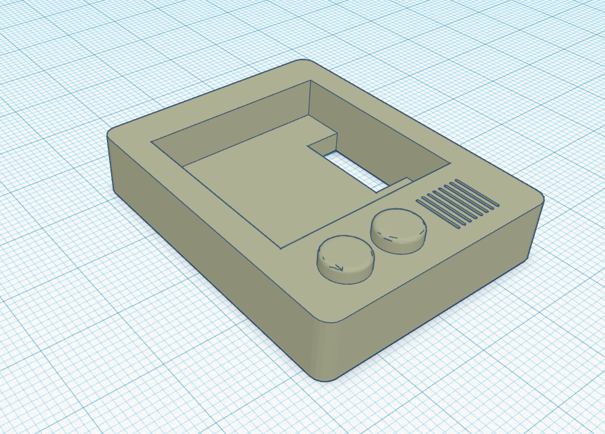
As a basis, we used an Arduino uno mini since it’s small enough to not blow up the proportions of the wearable but still had enough functionality for what we wanted to achieve. We then created a case for it based on this design with some walls and mounting points for connectors.
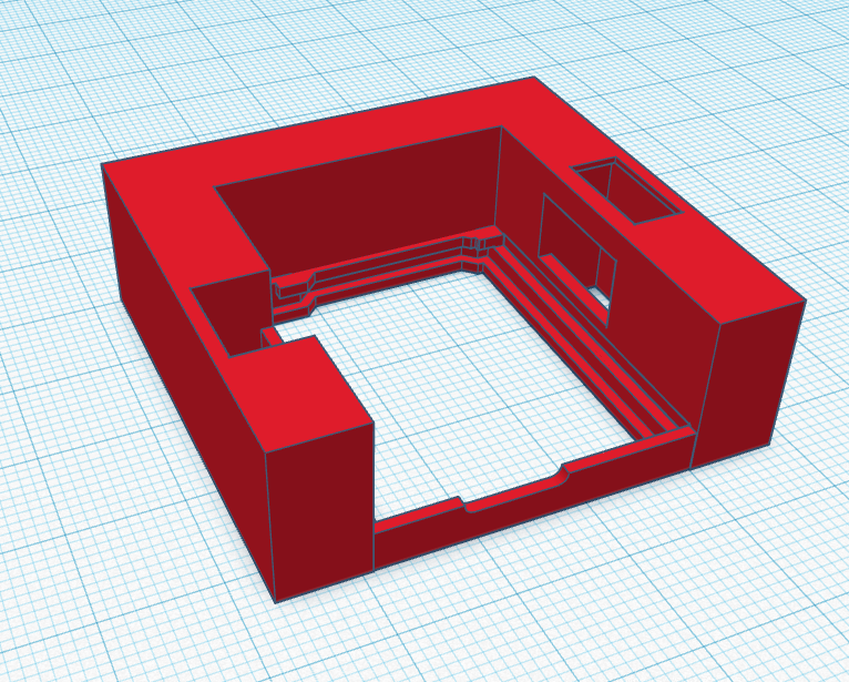
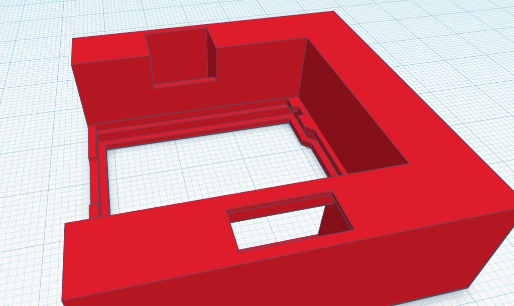
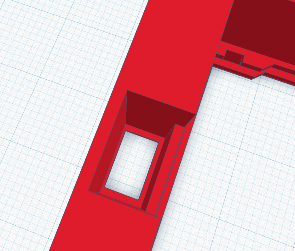
The Arduino would sit in the middle and through the holes, one connector would be placed on top and another on the bottom. The cables would be fed through the holes to the Arduino. We used connectors from an old kit I had lying around which we soldered wires to with solid metal cores so they would hold their shape when bent. This meant they would not move by themselves, staying connected and keeping the Arduino in its place.
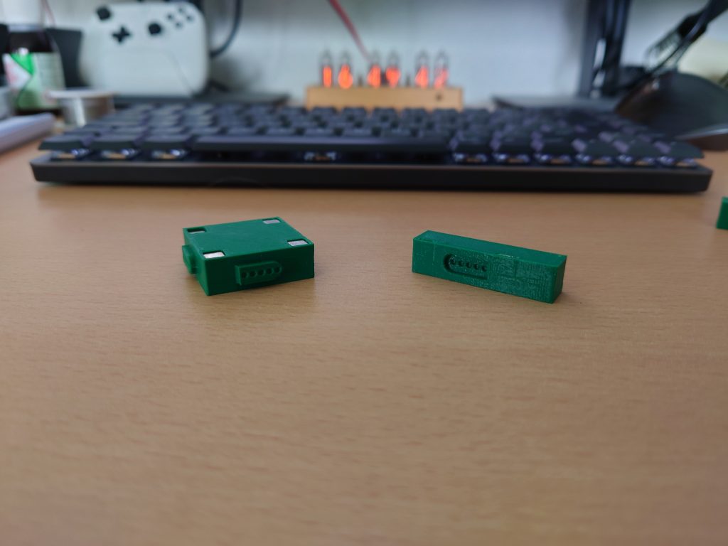
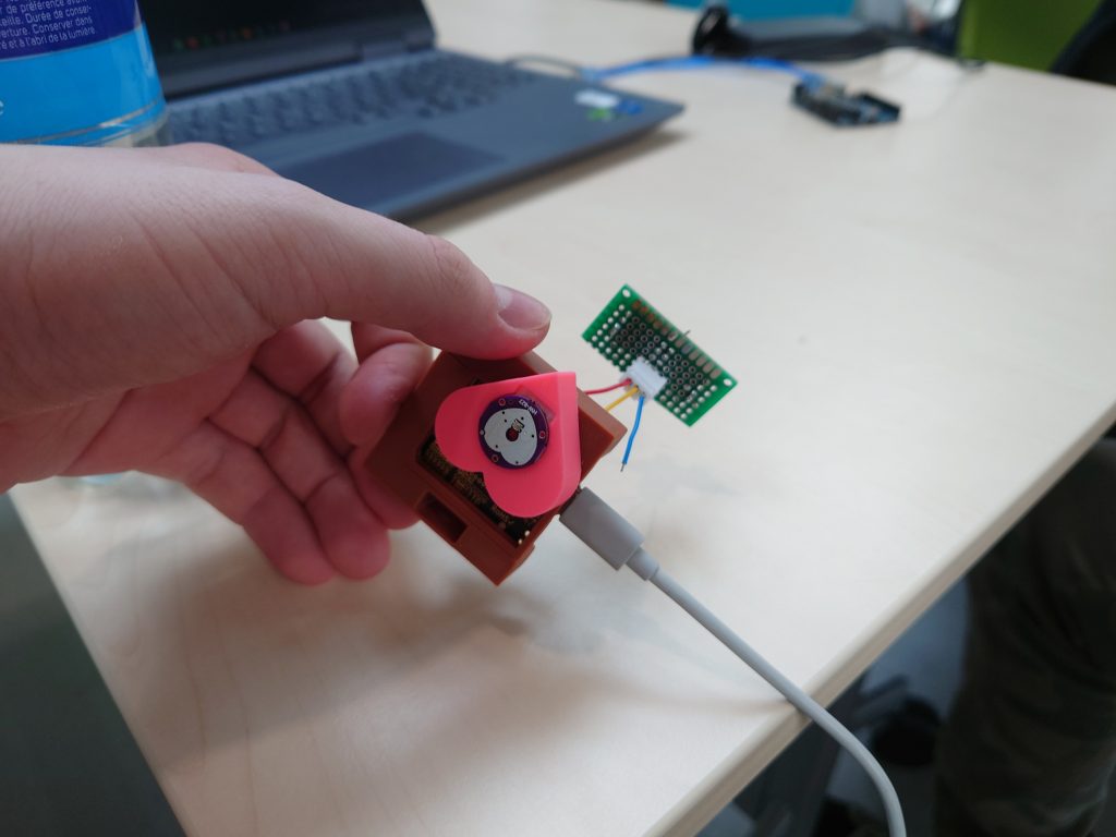
We created three modules to connect to the Arduino, although only two would connect to the connectors in its case. Due to time concerns we weren’t able to print a version of the case with another hole for the third connector. The two modules that connected to the connectors on the Arduino case were the display and the heartrate sensor. In keeping with the design we chose in refinement, these modules would get their own casings which communicate what their function is.
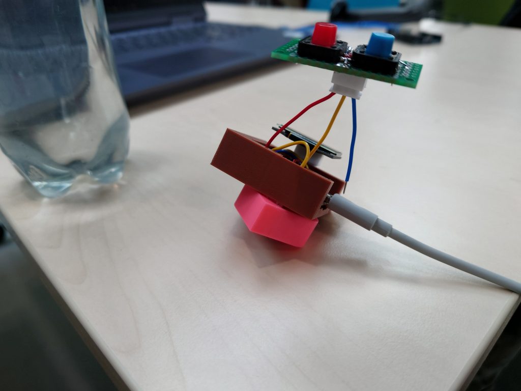
They used connectors with different pinouts so connecting the display to the heartrate connector or vice versa was impossible. This goes directly against the original idea but was done to protect the components and make the prototype less confusing to use. The final module we made was a small two-button pad to play a game on the display, it didn’t get a slot in the case, but was connectable through a connector.
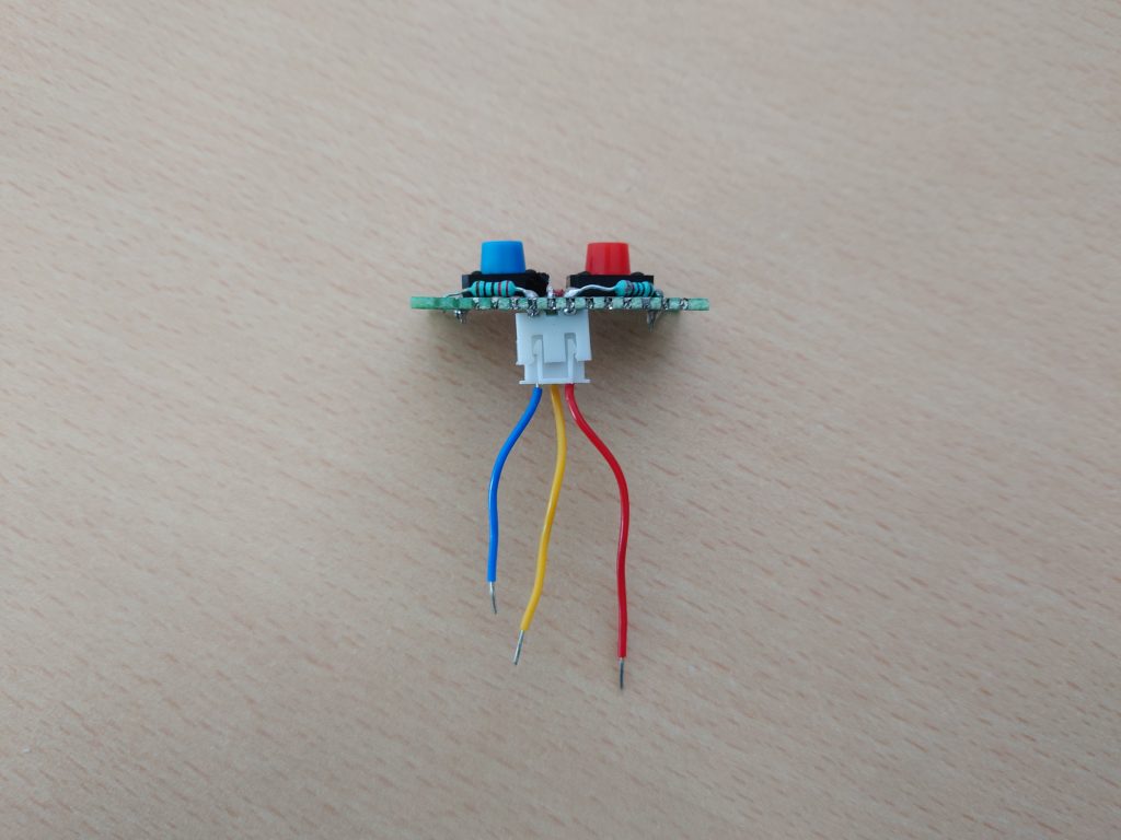
When everything was assembled, it looked like the images below (note, the display casing is missing from the third image and the blue wire is intentionally disconnected):
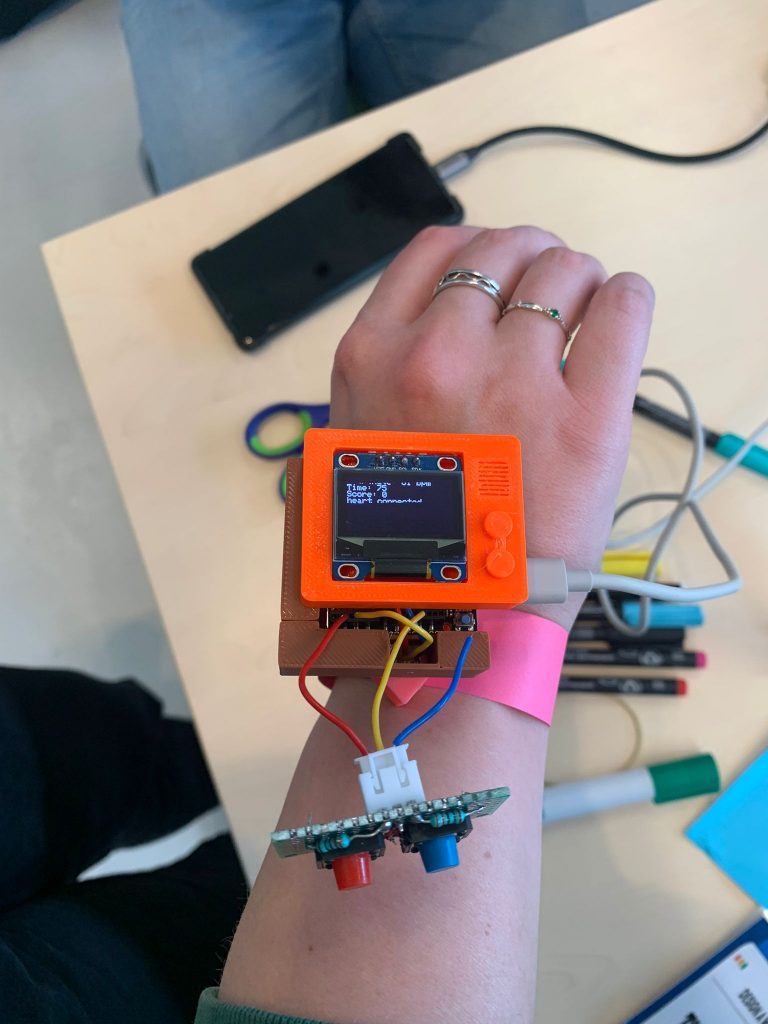
Users could disconnect the display, buttons and heartrate sensor and could play a little game on the display if the buttons and display were connected. To symbolise more modules we also added some cardboard pieces shaped after what those modules could look like (Bee as a buzzer, oxygen tank for a CO2 meter, ship’s compass for a compass, etc.). These let users envision more types of wearables than the actual prototype offered.
Evaluation and Reflection
The zip file contains a document with detailed evaluation of our project so I won’t go over that here. Looking at our prototype, as it stands it’s not particularly tinkerable in this state. You can take parts off and put them back but you can’t build something to your own vision. The cardboard modules help a lot and do give some idea of what we eventually would want to reach, but ask a lot of the user’s imagination. If we consider the project as if we had the material we envisioned in the earlier steps, things start to look more tinkerable. A kit with 20+ modules users could slot in where they want does open the door to more customisation and building what you want. However, there’s still a lot of restrictions on the material and the amount of different combinations one can make is low compared to something like Lego. I think, through developing this concept, we learned that the amount of different combinations you should be able to make should be immense before it feels like a material really lets you free to experiment. This is why we also looked at second “tinkering layers” (I talk about this a bit more here) like modules that can accept their own parts like cardboard, and a software suite to better control module behaviour or develop small programs to run on the wearable. We weren’t able to make these since this prototype already took up all our time, but this would go a long way to create a material that is as tinkerable as the great materials we saw in this course. During the final session of the course, we saw the scaffolding materials we developed around the material do a good job introducing the material and getting people comfortable working with electronics on such a small scale. If the material would get updated with more tinkering layers, the scaffolding may need additional steps (especially for the software part) but the steps right now appear a great match for the material. Thus, I feel we can conclude our material has a lot of potential to be a toolkit people could play with and learn a lot from, but it would need much development and expansion to get to that point.